
3D Block diagrams and texture mapping (using some non-free software)
For this exercise we will be making a diagram using adobe illustrator (not-free) and sketchup (free). We will create a blank rectangular prism in sketchup and then make textures to add to faces using adobe illustrator. Texture is the 3D modelling term for the surface detail (image) of an object.
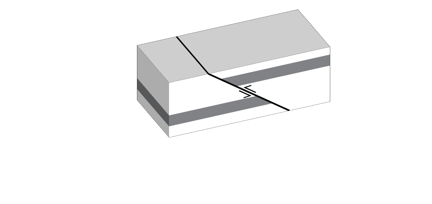
Concept stage
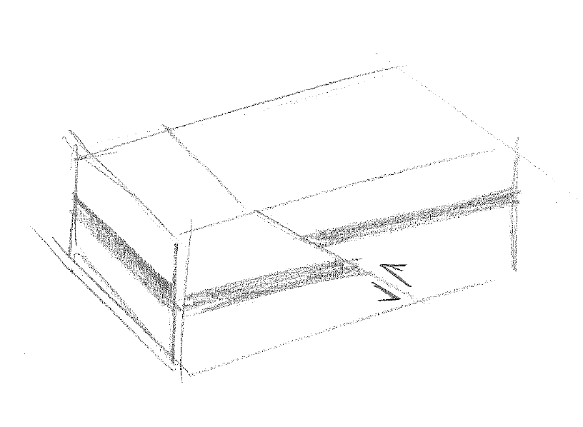
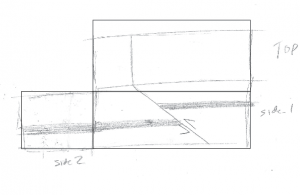
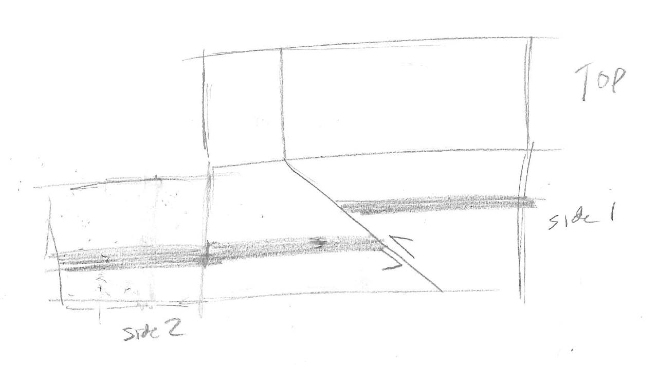
Start by drawing a sketch of the model you want to make. In this example I will be making a simple model of a reverse fault. You should make a different kind of model. Here is the sketch I drew to guide the model.
Make the blank rectangular prism in Sketchup
It’s a good idea to look around for an intro sketchup tutorial for the OS and software version you are using before you get started. The general workflow in sketchup is to draw in 2D and then extrude (give things depth). Sketchup has a very easy to use UI for doing texture mapping (putting surface images onto objects). But some of the drawing tools are a bit tricky to use.
Setting up the template view
When you open sketchup you will see a splash screen that prompts you to choose which type of environment you want to use. For diagrams we want to use either woodworking or 3D printing with mm units. You can set this as the default via “Window>preferences>Template”
Draw a rectangular prism
Measure the length of the sides of the concept sketch you drew. It’s a good idea to decide now how big the model is going to be and scale accordingly, but keep the aspect ratio the same. The rectangular prism I will draw is 50mm by 110mm on the base and 40mm high.
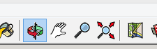
- In sketchup click on the shapes tool and then choose the Rectangle tool from the dropdown menu.
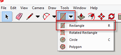
- The red, green and blue lines represent the Cartesian (x, y and z axes). The origin is where these lines intersect. Click once with the rectangle tool in the origin.

- Now when you move the cursor around you will see a rectangle being drawn in the x, y plane.
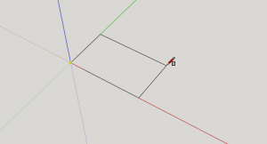
- We want this rectangle to match the base dimensions of our rectangular prism. In my case that is 50mm by 110mm. Notice the dimensions shown in the lower right of the sketchup window. I could resize until it I get the required dimensions. But it is generally easier to type the dimensions in. You need to match the dimension format shown e.g. “110mm, 50mm” then press enter. You don’t need to put the cursor in the dimensions box to start typing in there.
- This is where things get a bit tricky in sketchup. It’s not as easy to set precise measurements after you’ve drawn an object (as far as I can tell). So it’s best to put them in before you have finished then hit the enter key. If you muck up, just start again.
- Now we need to extrude the object using the push/pull tool

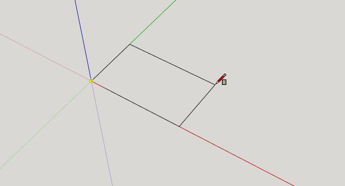
- To get precise dimensions we need to click once on the object. Move the cursor up a bit to extrude and then type the dimensions in. In my case that is 40mm.
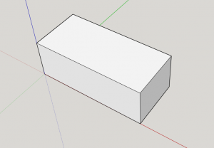
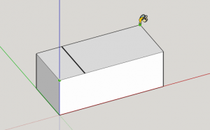
- Now we have our blank rectangular prism.
- Rotate around the model to have a look at it using the rotate tool.
Tip: If you muck up the drawing you can use undo to go backwards or select an entire object by clicking and dragging over the entire object (rubber band selection paradigm) and then delete it and start over. - Save your model now.

Change the view to orthographic (Parallel projection)
Q: By default which type of view (perspective or orthographic) is being used in sketchup?
A:
- Change the view to Orthographic (parallel projection) via Camera>Parallel projection.
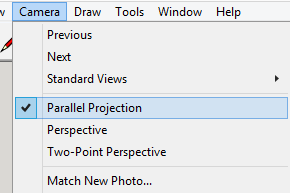
- Note the differences between parallel (ortho) and perspective view.
Make the textures using adobe illustrator
If you haven’t used illustrator before it’s a good idea to go over an introductory tutorial such as this one:
Now we need to draw the textures (images) that will go on the faces of our blank rectangular prisms. We only need to make textures for three faces corresponding to the visible faces of the model.
Sketch and digitising stage
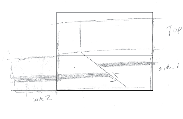
- Start by sketching what the three faces should look like as if you have unfolded the box of the sketch you made. You can scan this sketch in and work directly from it in illustrator (modifying dimensions to match the model).

- Open up illustrator and start with an A4 landscape document (or similar).
- Start by adding in your scanned sketch (if you like).
- We will start by drawing rectangles for the three sides of your rectangular diagram.
- Use the rectangle tool and click and drag to make a rectangle

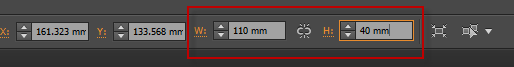
- Unlike sketchup, it’s pretty easy to change the size of a rectangle after you have drawn it using the control panel at the top of the window. Uncheck the aspect ratio lock and then set the dimensions to match one of the faces of your rectangle.
- Repeat 5-6 for the other two rectangles.
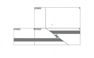
- Arrange the rectangles so that they are touching along the shared sides. You should have something like this:
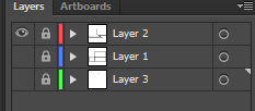
- To make things a bit easier we will lock this layer and draw the face details in another layer. Go to the layers panel, create a new layer (by clicking on the page icon) and then lock the bottom layer.
- Digitise the sketch you made in this layer. You will most likely need to use the pen tool to create lines and maybe the rectangle tool.

- The direct selection tool is useful for moving nodes along a path

- Set fill and stroke as required in the tools panel. (double click to change).

Exporting the faces
The next feature we will be utilising in illustrator is artboards. Artboards allow you to have multiple views of a single artwork that export separately. We will be using a different artboard for each face of the cube. (i.e. matching the rectangles we have drawn).
- First make sure all the layers are locked (moving artboards sometimes moves content).
- Now Click on the artboards tool.

- Click on new artboards and adjust the size and position to match the rectangular faces you drew.

- You should now have something like this:

Tip: an alternative approach is to draw the artboards first and not draw rectangles for the faces at all
Exporting the faces of the diagram
- Turn off the rectangle layers
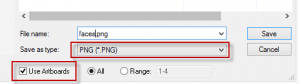
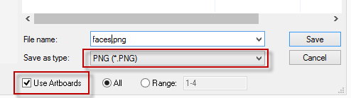
- Go to file>export and choose PNG format and check use artboards.
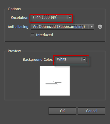
- On the next screen set the resolution to 300ppi and choose background colour white. We don’t want to use transparency in this case (but may be useful in other situations).

- Have a look at the files you have just made.
Mapping the textures in sketchup
- Open up your sketchup model you made earlier
- Go to file>import
- Choose one of the texture faces that you made and click the option “use as texture”
- Click and drag from one corner on the correct face to the opposite corner to map the texture
- Repeat for the other faces/textures
- This is what you should have now:
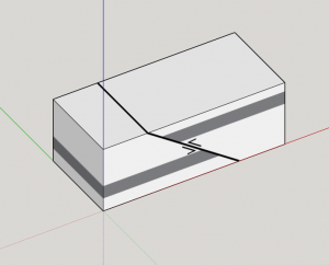
- Save your model.


Export the model
The final stage is rendering (exporting the 3D model).
- Use the rotate tool to choose a good view point
- Zoom in on the model
- Turn off axes if you like (View>axes)
- Go to file> Export>2d Graphic
- Go to options (lower right), uncheck Use view size and change it to whatever size you want.
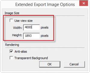
- Click Ok and then export
- Finished!
It’s often easier and quicker to draw the entire diagram in illustrator within a single perspective. But the approach I demonstrate here produces the most accurate 3D effect.
Back to: 3D Geology diagram techniques